
AMR heavy drive
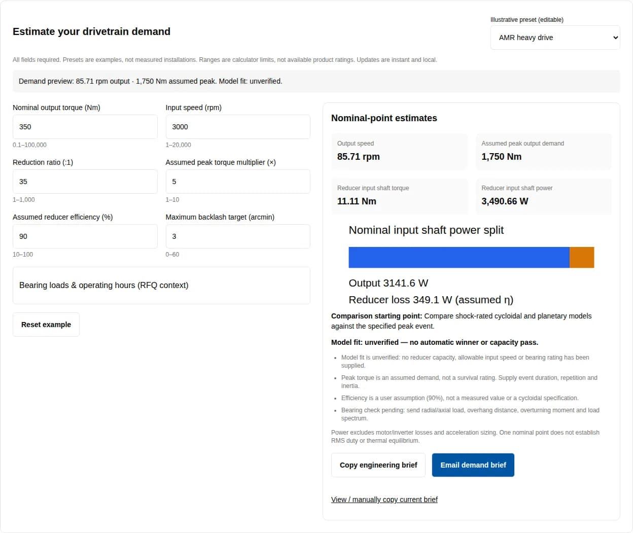
Assume 350 Nm output, 3000 rpm input, 35:1 and 5× peak; η = 90%.
Demand: 85.71 rpm, 1,750 Nm peak and 3,490.66 W input.
Next check: Provide wheel overhang and peak event counts; compare shock-rated cycloidal and planetary assemblies.
Demand calculator + evidence guide
Compare the advantages of cycloidal gearboxes over traditional gear mechanisms. Estimate speed, torque and power; model capacity needs product data.
Comparison starting point: Compare shock-rated cycloidal and planetary models against the specified peak event.
Model fit: unverified — no automatic winner or capacity pass.
Power excludes motor/inverter losses and acceleration sizing. One nominal point does not establish RMS duty or thermal equilibrium.
By AMRGearbox, the site publisher. Published , reviewed . Method: manufacturer-source review and reproducible shaft-power arithmetic; no independent hardware test is claimed.
Choose a reducer against a duty cycle and installation, then compare mechanisms. The advantages of cycloidal gearboxes over traditional gear mechanisms are conditional: geometry can support compact reduction and distributed contact, while the complete assembly determines load capacity, precision and service requirements.
Scroll horizontally to compare all columns. Keyboard: focus this table area and use the arrow keys.
| Decision | Evidence | What remains to verify |
|---|---|---|
| Shock-intensive duty | Named Cyclo product family advertises momentary overload capability (Sumitomo). | Exact model, peak duration and repetition; no universal 500% allowance. |
| High reduction in limited space | Cyclo Overhead family lists single-stage ratios to 119:1 (Sumitomo). | Installed envelope, input stage and available ratio for the actual model. |
| Precision motion | Nabtesco distinguishes lost motion and rated performance; strain-wave is another precision option. | Test torque, stiffness, hysteresis and loaded motion accuracy. |
| Wheel or turntable support | Cyclo catalog selection checks overhung load by frame and load position. | Bearing arrangement, overhang and combined force/moment limits. |
Sources: Sumitomo — Cyclo Overhead Drive; Sumitomo — Cyclo 6000 catalog, output overhung loads §§5.8–5.9; Nabtesco — Precision Reduction Gear product guide. These sources describe other manufacturers’ products, not verified AMRGearbox specifications.
A cycloidal arrangement uses an eccentric-driven disc and ring contacts to obtain reduction, with an output carrier extracting the disc motion. Involute trains transmit load through gear meshes and, in planetary layouts, through multiple planet paths. Both need suitable contact stresses, bearings, materials and lubrication. Neither architecture eliminates fatigue or damage.
Contact sharing depends on profile, clearances and elastic deformation. This guide does not assign a universal percentage of engaged pins, compare a contact stress directly with tooth-root bending stress, or predict competitor failure from the topology name.
Scroll horizontally to compare all columns. Keyboard: focus this table area and use the arrow keys.
| Mechanism | Reason to investigate | Evidence to request |
|---|---|---|
| Cycloidal | High reduction or shock-duty candidate; precision and industrial variants differ. | Continuous/repeated/emergency torque, input-speed limit, lost motion and bearing support. |
| Planetary | Coaxial alternative; compare stage count and actual installation requirements. | Ratio-specific efficiency, precision grade, planet load sharing and output bearing data. |
| Strain-wave | Compact high reduction and zero-backlash gear mesh (Harmonic Drive). | Loaded stiffness, permitted peak cycles, assembly bearings and life conditions. |
| Spur / helical | Compare where a conventional train meets layout and duty needs. | Stage layout, root/contact ratings, noise and lubrication requirements. |
| Worm | Investigate when a right-angle arrangement suits the installation. | Duty-point efficiency, heat rejection, wear and backdriving/holding behavior. |
Harmonic Drive — Strain Wave Gear Principle supports the strain-wave alternative. The other shortlist considerations are screening questions, not comparative test results. Price, lead time and total ownership cost are unknown until equivalent RFQs are obtained.
Scroll horizontally to compare all columns. Keyboard: focus this table area and use the arrow keys.
| Output | Equation | Assumption / limit |
|---|---|---|
| Output speed n₂ (rpm) | n₂ = n₁ / i | i is the total reduction magnitude; direction is excluded. |
| Output power P₂ (W) | P₂ = T₂ × 2π × n₂ / 60 | Nominal torque and speed at the same operating point. |
| Input shaft power P₁ (W) | P₁ = P₂ / η | η is the user-entered mechanical efficiency / 100. |
| Input shaft torque T₁ (Nm) | T₁ = T₂ / (i × η) | No motor inertia, start friction or acceleration allowance. |
| Peak output demand (Nm) | Tpeak = T₂ × k | k is an assumed multiplier, not a verified capacity. |
| Reducer loss (W) | Ploss = P₁ − P₂ | At the nominal point only; not a thermal limit. |
For the default example, 350 Nm at 3,000 rpm input and 35:1 gives 85.71 rpm output, 3,141.59 W output and 3,490.66 W input at an assumed 90% efficiency. The assumed 5× peak is 1,750 Nm. These values describe demand; they do not specify a suitable gearbox. Calculations retain full precision until display.
With 30 disc lobes and 31 stationary pins in the usual one-lobe-difference arrangement, the disc output speed magnitude is 1/30 of the eccentric input, so reduction magnitude is 30:1. A pre-stage changes the total ratio. The calculator accepts total ratio directly; it does not synthesize a disc profile.
Hertz contact stress, tooth-root stress, bearing life and capacity pass/fail are not calculated. Geometry, material properties, bearing identity and a measured load spectrum are missing. ISO 6336-1:2019 — Spur and helical gear load capacity describes involute gear calculation scope; it cannot certify a cycloidal design.
An emergency event and repeated start/stop operation require separate limits. Ask the supplier to evaluate peak duration, cycle count, input inertia, braking and the connected structure, not only the highest torque. A high momentary limit is not permission to repeat that event continuously. See Nabtesco — Precision Reduction Gear product guide for the terminology.
For an AMR wheel, send wheel radius, vehicle load distribution, obstacle geometry, speed, traction limit and stopping profile. For a lift, add the load-holding function and brake assessment. The tool does not validate a machine safety function or prescribe a universal stopping deceleration.
Scroll horizontally to compare all columns. Keyboard: focus this table area and use the arrow keys.
| Assumed efficiency | Reducer input power | Reducer loss at nominal point |
|---|---|---|
| 80% | 3,926.99 W | 785.4 W |
| 90% | 3,490.66 W | 349.07 W |
| 95% | 3,306.94 W | 165.35 W |
Request efficiency at the actual torque-speed-temperature point, plus no-load drag and start torque where they matter. Select lubricant, fill and maintenance interval from the chosen model’s instructions. Film thickness, maximum speed and lubricant lifetime are unknown here; there is no universal grease recommendation.
Compare equivalent quoted assemblies, including output bearings, brake, motor adapter, seals, spares and test effort. To estimate energy cost, integrate input power over the actual operating cycle and apply your tariff. Hours/day alone cannot establish energy savings or a payback period.
Backlash, lost motion and torsional stiffness answer different questions. Request the measurement torque, fixture, load direction, temperature and run-in state, then compare like-for-like data. A zero-backlash mesh can still have elastic deflection and assembly hysteresis. Nabtesco — Precision Reduction Gear product guide provides lost-motion terminology; Harmonic Drive — Strain Wave Gear Principle describes a zero-backlash alternative.
No public evidence checked for this page establishes a universal sub-1 arcmin retention curve over 10,000 hours. Ask for application-relevant endurance data with sample count and acceptance limits. The tool records your precision target without declaring that any mechanism meets it.
Scroll horizontally to compare all columns. Keyboard: focus this table area and use the arrow keys.
| Risk | Consequence | Mitigation / alternative |
|---|---|---|
| Overload allowance mistaken for continuous torque | Fatigue or thermal limit may be exceeded. | Verify separate continuous, repeated peak and emergency ratings. |
| Radial force supplied without load position | Output support may be incorrectly sized. | Provide overhang/moment; compare an externally supported shaft option. |
| Backlash used as loaded accuracy | Position or settling requirement may be missed. | Request stiffness/hysteresis measurements and a loaded motion test. |
| Low purchase price compared across unlike assemblies | Bearings, brakes or service costs may be omitted. | Normalize RFQ scope, warranty conditions, spares and maintenance. |
| Holding assumed from reduction mechanism | Uncontrolled motion under some conditions. | Assess an independent brake/holding system and test the whole load path. |
| Nominal point treated as full duty cycle | RMS torque, peak cycles or thermal duty may be missed. | Supply a torque-speed-time trace; compare alternative mechanisms at that cycle. |
These are worked assumptions, not customer installations or measured performance. Use each preset above to reproduce the demand. No gearbox model, reliability gain or cost saving is asserted.
Assume 350 Nm output, 3000 rpm input, 35:1 and 5× peak; η = 90%.
Demand: 85.71 rpm, 1,750 Nm peak and 3,490.66 W input.
Next check: Provide wheel overhang and peak event counts; compare shock-rated cycloidal and planetary assemblies.
Assume 180 Nm output, 2500 rpm input, 59:1 and 3.5× peak; η = 90%.
Demand: 42.37 rpm, 630 Nm peak and 887.46 W input.
Next check: Request lost-motion/stiffness data at the joint load; include precision planetary and strain-wave alternatives.
Assume 620 Nm output, 2000 rpm input, 43:1 and 2.5× peak; η = 90%.
Demand: 46.51 rpm, 1,550 Nm peak and 3,355.36 W input.
Next check: Verify axial force, overturning moment and output bearing arrangement before judging angular precision.
Assume 850 Nm output, 3000 rpm input, 87:1 and 4× peak; η = 90%.
Demand: 34.48 rpm, 3,400 Nm peak and 3,410.41 W input.
Next check: Specify brake/holding function and evaluate the complete lifting load path.
Sources checked . Product references are manufacturer publications, not an independent equal-size comparison. Standards links verify their public scope only; no compliance certification is claimed. Reconfirm revisions and selection sheets before procurement.
Explains the eccentric RV stage, ring pins and input spur reduction stage.
Boundary: Architecture reference for the named RV construction; not every cycloidal unit has the same output arrangement.
This named family advertises 500% momentary shock capacity and single-stage ratios to 119:1.
Boundary: Manufacturer product statement, not a rating for all cycloidal units or our supplied products; confirm the selected model and event limits.
Overhung load selection uses frame-specific limits and load location factors.
Boundary: Radial force alone is insufficient; include load position and the chosen frame. Catalog edition v12 (2025 URL); obtain the latest selection sheet before ordering.
Guide terminology separates rated torque, acceleration/deceleration torque, momentary maximum torque and lost motion.
Boundary: Use the exact model, ratio, test condition and current catalog revision. These are distinct checks, not interchangeable overload allowances.
Strain-wave gearing is an alternative with zero-backlash gear mesh and compact high reduction.
Boundary: Gear-mesh backlash does not describe complete assembly compliance, bearing capacity or application life.
Scope covers cylindrical straight/helical involute gears and calculation influence factors.
Boundary: This is not a direct cycloidal rating method, nor assurance of an assembled drive system.
Basic bearing rating life uses defined bearing/load conditions and 90% reliability.
Boundary: A statistical fatigue-life calculation is not guaranteed gearbox service life. Wear, corrosion and electrical erosion are outside its stated coverage.
Known: user requirements and reproducible nominal-point equations. Unknown / pending confirmation: selected model, continuous/repeated/emergency ratings, measured efficiency, bearing capacity, lifetime, lubricant interval, price and delivery. No public evidence here supports a universal ranking across all five mechanisms.
Cycloidal designs are worth comparing for compact high reduction, distributed contact and shock-duty applications. Precision variants can support tight motion requirements. These advantages depend on the selected construction; compare actual torque, lost motion, thermal and bearing data rather than assuming every cycloidal unit is superior.
No. Sumitomo advertises 500% momentary shock capacity for its named Cyclo Overhead Drive family. That claim is not a continuous rating or a transferable guarantee for other models. Confirm duration, event count and the exact selection sheet (source: Sumitomo in the evidence ledger).
No. It estimates demand at one nominal operating point and prepares an RFQ brief. Capacity, fatigue, holding safety and thermal suitability remain unverified until a supplier reviews model data and the complete load cycle.
It is an explicit assumption for reducer mechanical efficiency, initially 90% for illustration. Replace it with a model-specific value at the stated load, speed and temperature. It excludes motor, inverter and electrical losses.
No. Continuous, repeated acceleration/deceleration and emergency peak limits refer to different conditions. Request duration and permitted event counts for each limit (source: Nabtesco product guide in the evidence ledger).
No. Compare installation envelope, available ratios, input speed, efficiency at the duty point, stiffness, cost and support. A planetary model may satisfy the same requirement. This page provides no universal topology ranking.
Include it when compact high reduction and a zero-backlash gear mesh are important. Harmonic Drive describes these benefits in its technology reference. Check the whole assembly for torsional compliance, output support and overload capability (see the evidence ledger).
No. Clearance, elastic deflection and hysteresis affect different measurements. Ask for test torque, load direction, fixture stiffness and temperature when comparing results. A single backlash number cannot predict loaded positioning accuracy.
No. It lacks bearing identity, dynamic rating, equivalent load factors, geometry, material data and contact load distribution. Those outputs are deliberately withheld; send these data for an engineering calculation.
They are included in the brief and trigger a bearing-review reminder. They do not alter the torque/power equations or prove a bearing pass. Provide overhang distance, overturning moment and the load cycle as well.
No. Hours/day is RFQ context. Service life also depends on operating loads, cycles, speed, lubrication and failure criteria. A statistical bearing life should not be presented as guaranteed gearbox lifetime (see ISO 281 in the evidence ledger).
Do not assume holding capability from topology. Specify the load-holding function, backdriving conditions and an assessed brake/holding system. Test the assembled machine under the relevant safety requirements.
Use the selected manufacturer’s lubricant, fill quantity, mounting orientation and maintenance instructions. This page has no verified universal lubricant, film thickness or sealed-for-life interval for cycloidal units.
No. ISO 6336 addresses involute spur/helical gear load capacity; ISO 281 addresses rolling bearing rating life. Neither provides a blanket cycloidal superiority certificate or validates this demand estimator (see the linked ISO scopes).
No. They are illustrative scenarios using editable assumptions. Their outputs show nominal kinematics and demand, not field reliability, noise, savings or model validation.
Send the tool brief, CAD envelope, overhang and mounting drawing, torque-speed cycle, peak-event duration and count, ambient temperature, precision test requirement, desired life, quantity and delivery destination. Ask for evidence against continuous, repeated peak, emergency peak, thermal and bearing limits.
Send the current demand brief with mounting drawings, torque-speed-time cycle, target life, environment, quantity and delivery destination. Ask for model-specific evidence for continuous torque, repeated peaks, emergency events, thermal duty, precision and output support.
Direct contact: [email protected]. Email opens your mail app; the inquiry form is available if no mail app is configured.