

Sizing AMR Gearboxes for Mobile Manipulators (MoMos): Managing Asymmetric Dynamic Loads
Use this AMR gearbox sizing guide to estimate MoMo overturning moments, radial loads, stiffness needs, and RFQ specs for cobot-equipped AMRs.
The integration of Collaborative Robots (Cobots) with Autonomous Mobile Robots (AMRs) has given rise to a highly versatile class of automation: the Mobile Manipulator (MoMo). For AMR gearbox sizing, that makes MoMos a separate drivetrain load case rather than a taller logistics AMR. These hybrid systems can navigate factory floors, visually identify parts, pick them up, and transport them to the next workstation.
However, from a mechanical engineering and procurement perspective, mounting a 6-axis robotic arm on top of a standard differential-drive AMR chassis introduces severe mechanical stress. A standard AMR is designed to carry a static, centered, and symmetric payload (like a pallet or a bin). A Mobile Manipulator, by contrast, operates with an active, shifting, and highly asymmetric center of gravity.
When the robotic arm extends fully to the side to pick up a heavy payload, it creates a massive overturning moment. This force bypasses the chassis suspension and transfers directly into the wheel drive modules—specifically, the output bearings and the gears of the propulsion gearboxes.
Procurement teams buying standard "off-the-shelf" AMR gearboxes for MoMo applications frequently experience catastrophic premature bearing failures, gear tooth shear, or unacceptable chassis deflection during precision picking operations.
In this guide, we break down the mechanics of asymmetric dynamic loading, how it affects gearbox lifespan, and what specifications engineers must prioritize when sourcing gearboxes for Mobile Manipulators.
Scope and date: Updated July 24, 2026, for global automation engineers, hardware designers, and procurement teams building or sourcing drive modules for Mobile Manipulators. The metrics and calculations provided are for general sizing reference; always perform a complete FEA and dynamic multi-body simulation based on your specific cobot's reach, payload, and the AMR's wheelbase.
1. The Mechanics of the MoMo: Overturning Moments Explained
To understand why gearboxes fail in MoMo applications, we must first look at the static and dynamic forces at play.
In a standard AMR, the payload rests evenly on the chassis. The downward force ($F_z$) is distributed symmetrically across the drive wheels and casters. The gearbox output shaft primarily handles the tractive torque required to move the robot forward, plus a manageable static radial load.
When you add a robotic arm, the physics change dramatically. Consider a MoMo equipped with a cobot arm that has a 1.3-meter maximum reach and a 15 kg payload capacity. The arm itself might weigh 40 kg.
When the arm rotates 90 degrees to the direction of travel and extends to its maximum reach to pick up a 15 kg part, the center of gravity shifts drastically outside the AMR's footprint.
This creates an Overturning Moment ($M_x$ or $M_y$). The formula is straightforward:
M = (W_arm * D_arm) + (W_payload * D_reach)
Where:
W_arm= Weight force of the extended arm segmentsD_arm= Distance to the arm's center of massW_payload= Weight force of the payloadD_reach= Distance to the payload (reach)
For a preliminary supplier screen, use the formula before requesting detailed CAD or FEA. In the 40 kg arm + 15 kg payload example above, assume the arm center of mass is 0.65 m from the chassis centerline, the payload is 1.3 m out, and the lateral track width between drive wheels is 0.55 m:
- Static overturning moment: $(40 \times 9.81 \times 0.65) + (15 \times 9.81 \times 1.3) \approx 446 N·m$
- Incremental load transfer to the loaded-side drive module: $446 / 0.55 \approx 811 N$
- Shock-screening load before final validation: $811 N \times 3 \approx 2.4 kN$, plus that wheel's normal static share of vehicle weight
This is not a final bearing-life calculation. It is a procurement filter: if a supplier cannot state dynamic radial load, moment-load, and shock-load ratings above this screening case, the gearbox should not move into prototype sourcing.
This moment acts as a lever, trying to tip the robot over. The chassis suspension resists this, but ultimately, the reaction forces are absorbed by the wheel drive modules on the loaded side. The wheel on the side of the extended arm experiences a massive spike in downward Radial Load (F_r), while the opposite wheel may experience a lifting force, reducing traction.
2. Why Standard AMR Gearboxes Fail
Standard planetary gearboxes used in logistics AMRs are optimized for tractive torque (pushing/pulling force) and use standard deep-groove ball bearings on the output shaft to support the vehicle's weight.
When a standard gearbox is used in a MoMo application, three distinct failure modes occur:
A. Output Bearing Brinelling and Spalling
When the cobot arm extends, the radial load on the gearbox bearing often exceeds its dynamic load rating. If the robot travels over an uneven floor or a threshold while the arm is extended, the impact creates a massive shock load. This forces the bearing balls into the raceway, causing permanent indentations (brinelling). Over time, this leads to spalling (flaking of the metal), rendering the gearbox noisy and eventually causing catastrophic seizure.
B. Gear Mesh Misalignment
The gearbox output shaft acts as a cantilever beam. Under extreme radial loads, the shaft deflects (bends) by fractions of a millimeter. This microscopic deflection propagates backward into the gearbox, causing the planetary gears to misalign with the ring gear. Instead of the gear teeth meshing evenly across their entire width, they mesh on the edges (edge loading). This concentrates the stress, rapidly accelerating gear wear and risking sheared teeth.
C. Chassis Deflection and SLAM / Vision Errors
For a MoMo to pick a part accurately, the chassis must act as a rigid base. If the gearbox bearings and output shaft lack sufficient stiffness, the entire robot will "sag" slightly towards the loaded side. A 0.5-degree sag at the gearbox level amplifies over the height of a 1.5-meter cobot arm, shifting the end-effector's position by centimeters. The onboard vision system will struggle to locate the part, leading to pick failures and cycle time degradation.
3. Upgrading the Architecture: What Makes a "MoMo-Ready" Gearbox?
To survive the asymmetric loads of a Mobile Manipulator, the drivetrain architecture must be fundamentally upgraded from a standard logistics AMR. Engineers and procurement teams should look for specific structural enhancements.
The Role of Cross-Roller Bearings (CRB)
The single most important upgrade for a MoMo gearbox is the integration of a Cross-Roller Bearing at the output stage, replacing standard ball bearings or tapered roller bearings.
In a CRB, cylindrical rollers are arranged crosswise, with each roller perpendicular to the adjacent one, separated by retainers. This design allows a single bearing to simultaneously handle heavy radial loads, axial loads, and overturning moments in all directions. Because the rollers make line contact with the raceways (rather than point contact like ball bearings), the rigidity is significantly higher, virtually eliminating output shaft deflection and preserving precision during heavy arm extensions.
Flange-Mount vs. Shaft-Mount
Standard AMR wheels are often mounted to a keyed output shaft. For MoMos, gearboxes must use a Flange-Mount design. A rotating output flange allows the wheel to be bolted directly to the gearbox face, keeping the load line directly over the bearings and minimizing the cantilever effect.
4. Selection Matrix: Standard vs. Heavy-Duty MoMo Gearboxes
When evaluating specifications, the differences between a standard AMR gearbox and a MoMo-ready gearbox are stark. Use this matrix to guide your procurement and design decisions:
| Specification / Feature | Standard Logistics AMR Gearbox | MoMo-Ready Heavy-Duty Gearbox | Impact on Mobile Manipulators |
|---|---|---|---|
| Primary Design Focus | Tractive Torque & High Efficiency | Radial Load Capacity & Stiffness | Prevents bearing failure during arm extension. |
| Output Bearing Type | Deep-groove ball or tapered roller | Integrated Cross-Roller Bearing (CRB) | CRBs handle multi-directional overturning moments. |
| Radial Load Capacity | Low to Medium (e.g., 2,000 N) | Extremely High (e.g., 8,000+ N) | Withstands the asymmetric weight shift of the payload. |
| Output Interface | Keyed Shaft | Flange Mount | Flange mount eliminates cantilever deflection. |
| Torsional Stiffness | Moderate | High to Very High | Prevents the robot from "sagging" or vibrating during precision picking. |
| Typical Architecture | Standard Planetary | Cycloidal or Precision Planetary w/ CRB | Cycloidal drives offer unmatched shock load resistance for MoMos. |
[!CAUTION] Dynamic Shock Loads: Never size a MoMo gearbox based solely on static load calculations. When a MoMo travels at 1.5 m/s over a 5mm floor expansion joint while carrying an asymmetric load, the dynamic shock load can peak at 3x to 5x the static load. Always select a gearbox with an emergency stop / shock load rating that exceeds these peaks.
5. Procurement & Engineering Checklist for MoMo Drivetrains
Before finalizing the BOM (Bill of Materials) for a Mobile Manipulator, run through this checklist with your drivetrain supplier to ensure long-term reliability:
- Calculate the Maximum Overturning Moment: Have you calculated the worst-case scenario (arm fully extended at 90 degrees with maximum payload)?
- Verify Dynamic Radial Load Ratings: Does the gearbox supplier's datasheet explicitly state the dynamic radial load (
F_r,dyn) capacity, and does it exceed your worst-case calculations? - Request Stiffness Data: Have you acquired the torsional and bending stiffness values of the gearbox to feed into your FEA/kinematic models to verify end-effector accuracy?
- Cross-Roller Bearing Verification: Does the gearbox utilize an integrated Cross-Roller Bearing or a heavy-duty dual angular contact bearing arrangement on the output?
- Shock Load Capacity: What is the gearbox's rating for emergency stops or impacts? (Look for ratings at least 2.5x the nominal torque).
- Floor Condition Profile: Have you mapped the deployment environment? (A MoMo deployed in a pristine semiconductor cleanroom can use tighter tolerances than one deployed in an automotive stamping plant with uneven concrete).
6. Related AMR Gearbox Decisions
Use the MoMo radial-load screen alongside these adjacent drivetrain checks:
- Gearbox MTBF for 24/7 autonomous robots - convert duty cycle and load assumptions into reliability targets.
- AMR gearbox backlash and SLAM accuracy - connect mechanical stiffness to localization and docking error budgets.
- ISO 3691-4 compliant AMR gearbox safety brakes - align drivetrain selection with braking and safety validation requirements.
7. Frequently Asked Questions (FAQ)
Q1: Can we use active suspension instead of heavier gearboxes?
Active or independent suspension can help keep all wheels on the ground, ensuring traction. However, the suspension spring/damper sits above the drive module. The wheel, bearing, and gearbox output shaft are unsprung mass and still bear the brunt of the lateral and radial forces generated by the overturning moment. Suspension does not replace the need for heavy-duty gearbox bearings.
Q2: Should we use Cycloidal or Planetary gearboxes for MoMos?
Both can work, provided they have a reinforced output bearing (like a CRB). However, Cycloidal gearboxes are generally preferred for MoMos in the 500kg+ class because their internal design (sharing load across many pins and rollers rather than a few gear teeth) provides superior resistance to shock loads and catastrophic tooth shear when driving over bumps with asymmetric loads.
Q3: How does gearbox stiffness affect the vision system?
If the gearbox bearings are "soft," the chassis tilts under load. The onboard cameras, usually calibrated to the chassis frame, will now be misaligned relative to the target part. While software can compensate slightly via fiducial markers, mechanical rigidity at the drivetrain level drastically reduces the computational overhead and error rate of the vision system.
8. Conclusion
Mobile Manipulators represent a leap forward in manufacturing flexibility, but they demand a completely different approach to chassis and drivetrain engineering. Treating a MoMo like a standard AMR with a cobot bolted on top is a guaranteed recipe for premature mechanical failure, high warranty costs, and unhappy end-users.
By understanding the physics of asymmetric loads, prioritizing Cross-Roller Bearings, and carefully matching dynamic radial load ratings, engineering teams can build MoMos that deliver pinpoint precision and decades of reliable service.
Sources / References
- ISO 3691-4:2023: Safety requirements and verification for driverless industrial trucks and AMR-style systems. iso.org
- ISO 10218-1:2025: Safety requirements for industrial robots, relevant when a MoMo integrates a cobot arm with a mobile base. iso.org
- THK Cross-Roller Ring technical overview: Cross-roller bearings can receive radial, axial, and moment loads in one compact bearing arrangement. thk.com
- SKF Bearing Maintenance Handbook: Bearing damage reference covering indentation, spalling, and field inspection patterns. skf.com
Designing a new Mobile Manipulator platform? Don't let your drivetrain become the weak link. Our engineering team specializes in sizing Cycloidal and high-precision Planetary gearboxes specifically for the rigorous demands of asymmetric MoMo loads. Request a technical consultation and sizing analysis via our AMR Gearbox RFQ Portal or contact us directly at [email protected].
Author
Categories
Need an AMR Gearbox Recommendation?
Reference this article and share your constraints. Our team replies via [email protected].
More Posts
AMR Gearbox Market Update: EU Brake and Cyber Audits
W27 AMR gearbox sourcing update: EU Machinery Regulation 2023/1230 applies Jan 14, 2027, forcing SBC brake evidence and cybersecurity audits for OEMs.

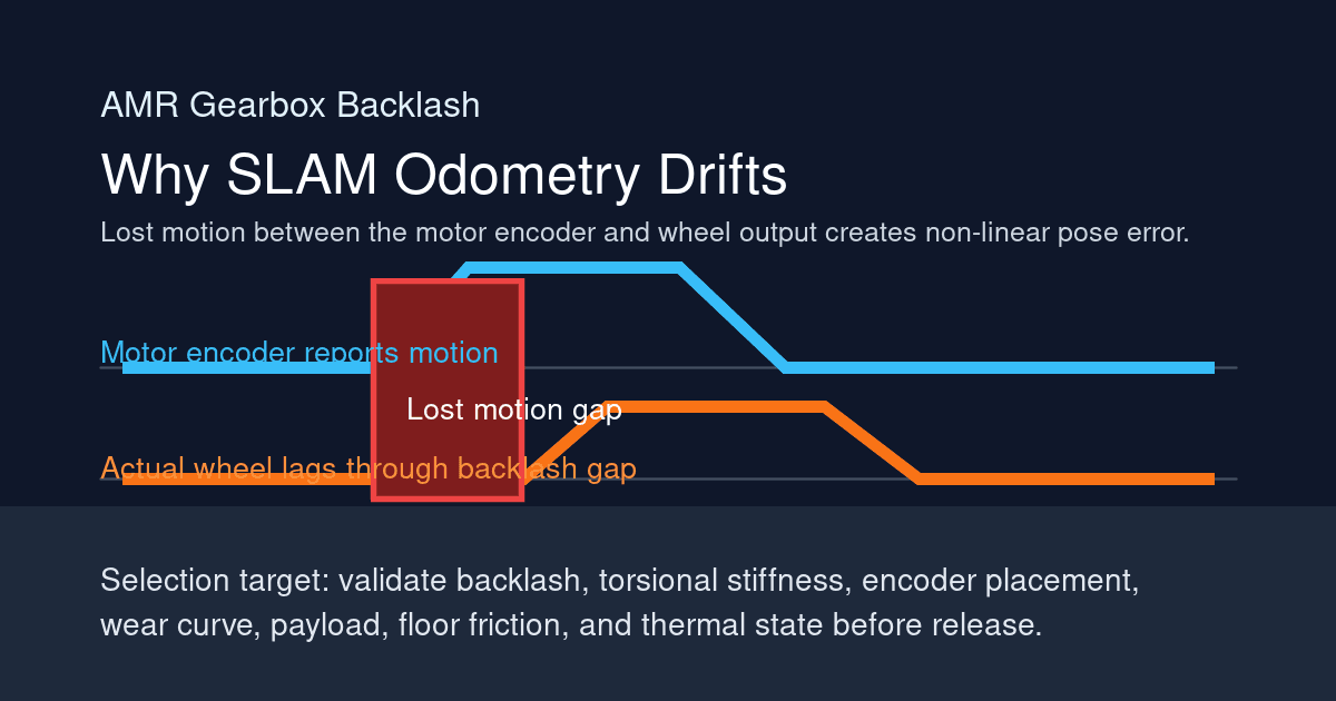
Solving SLAM Odometry Errors: How Gearbox Backlash Impacts AMR Navigation
How AMR gearbox backlash creates odometry drift, when SLAM can compensate, and what drivetrain specs engineers should request before buying.
AMR Gearbox Sourcing W30: 2026 Section 301 Tariffs
AMR gearbox sourcing guide for 2026 Section 301 tariff risk. Verify HTS codes, origin evidence, duty scope, and RFQ timing before supplier nomination.