
AMR Ramp, Incline & Dock Leveler Drivetrain Sizing: Overcoming Gradeability, Thermal Rise, and Dynamic Shock Loads
Size an AMR gearbox for ramps and dock levelers: compare climb torque, thermal duty, shock loads, and slope braking. Send your duty cycle for a sizing review.
Size an Autonomous Mobile Robot (AMR) gearbox for ramps and dock levelers by checking four separate loads: sustained climbing torque, heat over the complete mission, repeated transition shocks, and slope stopping/holding. A flat-floor torque calculation cannot establish gradeability. For the same laden mass and wheel radius, even an 8% incline can multiply the propulsion torque several times; the worked examples below show the assumptions and arithmetic.
A 30-second climb is longer than many acceleration peaks, but it does not by itself establish S1 duty or thermal equilibrium. Submit the climb duration, return descent, dwell, speed and repetition rate to the supplier. Likewise, a dock lip height alone cannot determine a shock multiplier or a safe crossing speed. Keep gearbox fatigue, output-bearing reactions, tire grip and the vehicle safety functions as separate approval checks.
Scope and review date: Reviewed 1 November 2026 for global AMR systems engineers, motion architects, and procurement teams. Metric SI units are applied throughout. This guide evaluates independently driven wheel architectures (differential, omnidirectional swerve, and central traction drives) operating on structured industrial concrete and steel dock surfaces. The worked calculation is hypothetical and reproducible, with no physical test or customer result claimed. It screens propulsion loads; approval also requires measured floor/tire behavior, load transfer, stability, a validated mission thermal model, and vehicle safety testing. It does not size the dock leveler structure or certify the complete robot.
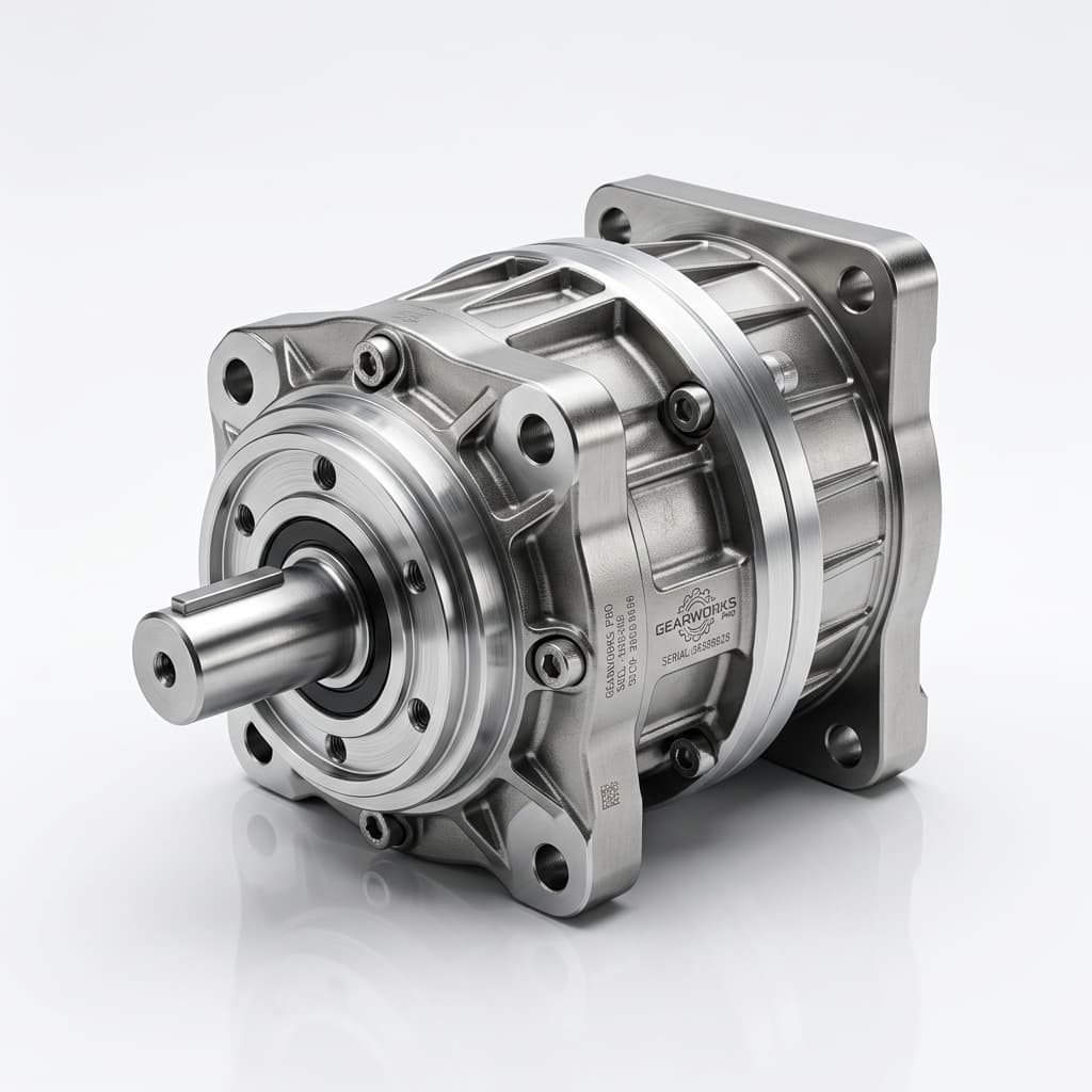
The cover image is an illustrative gearbox visual, not evidence of a tested ramp-qualified product. The inline schematic is qualitative and not drawn to scale.
If you are developing a ramp-capable warehouse robot or heavy-payload automated tugger, request a drivetrain sizing review with your chassis mass, payload envelope, incline geometry, and duty cycle.
1. The Physics of AMR Incline Navigation: Grade Force and Wheel Torque
When an AMR traverses a horizontal surface, the drive unit counteracts rolling resistance (F_roll) and dynamic acceleration forces (F_acc). On a ramp at angle θ relative to the horizontal plane, gravity decomposes into two orthogonal vectors: a weight component acting perpendicular into the floor plane, and a direct downhill grade resistance force acting parallel to the surface.
1.1 Mathematical Formulation of Total Tractive Effort
The total linear thrust force (F_total) required at the tire-floor contact interface during an ascent is modeled as:
F_total = F_grade + F_roll + F_acc + F_wind
For these indoor screening examples, aerodynamic drag (F_wind) is neglected. The individual load terms are defined as:
Grade Resistance Force (F_grade):
F_grade = m_total · g · sin(θ)
Where m_total is the gross laden mass (vehicle chassis plus maximum payload in kilograms), g is the gravitational acceleration (9.81 m/s^2), and θ is the slope angle in radians or degrees. Slope is frequently specified by facility planners as a percentage grade (G%):
θ = arctan((G%)/(100)) or sin(θ) ≈ (G%)/(100) (for small angles θ ≤ 10°)
Rolling Resistance Force on Incline (F_roll):
F_roll = m_total · g · cos(θ) · c_r
Where c_r is a dimensionless rolling-resistance coefficient. The values 0.018 and 0.020 used below are illustrative inputs, not measured tread/floor properties. Obtain rolling resistance at the actual wheel load, temperature and surface condition; tire hardness alone does not determine it.
Linear Acceleration Force on Incline (F_acc):
F_acc = m_total · a
Where a is the linear acceleration rate (m/s^2). Sizing for ramp navigation requires assessing whether the AMR must accelerate from a dead stop midway up the incline (hill-start) or whether it enters the ramp at cruising velocity (a = 0 m/s^2).
1.2 Wheel Torque and Speed Mapping to Gearbox Output
For a robot propelled by N identical driven wheels sharing traction equally, the required output torque (T_2) and rotational output speed (n_2) at each wheel drive gearbox flange are:
T_2 = (F_total · r_wheel)/(N · η_mech)
n_2 = (v · 60)/(2 π · r_wheel)
Where r_wheel is the effective rolling radius of the drive tire under full vertical deflection (in meters), v is the linear robot velocity (m/s), and η_mech is the mechanical efficiency of intermediate linkages, external hub bearings, or timing belt reductions (if direct-drive hub mounted, η_mech ≈ 1.0).
1.3 Traction and Load Transfer Can Limit Gradeability First
The total traction demand must stay below the tire-floor grip available at the driven wheels: F_total ≤ μ × ΣN_driven. Here μ is the tested traction coefficient and N_driven is the normal load on each driven wheel. Do not substitute the entire vehicle weight when casters carry part of the load. Uphill acceleration and a high payload center of gravity can unload a drive wheel; braking can reverse that transfer. Check the support polygon, wheelbase, payload restraint and approach/breakover clearance as well as motor torque. Equal torque sharing in the equations is an assumption to validate, especially for swerve modules or uneven dock plates.
2. Incline Kinematics, Wheel Reactions, and Threshold Shock Layout
The schematic identifies the weight components, wheel torque, holding torque and a dock-lip impact location. Bearing reactions and housing moments require a separate load calculation.
Figure 1: Qualitative ramp and dock-transition schematic. W_n is the weight component into the ramp; the floor normal reaction acts in the opposite direction. Slope angle and obstacle dimensions are not to scale; no reaction magnitudes are derived from this drawing.
3. Climb Duration, Repeated Duty, and Thermal Rise
Supplier torque labels are not interchangeable. Nominal torque, acceleration torque and emergency-stop torque each have their own speed, life, event-count and temperature conditions. A rare emergency-stop allowance cannot approve a shock repeated at every dock crossing. The Neugart NGV technical tables, for example, list nominal, maximum and emergency-stop torques separately, alongside thermal input-speed limits. Use the selected ratio and size, not the largest figure in a series.
3.1 Reproducible Flat-to-Ramp Comparison
For a hypothetical 1,500 kg vehicle, 0.100 m loaded wheel radius, two equally loaded drives, c_r = 0.018 and no external transmission loss:
T_flat = 1500 × 9.81 × 0.018 × 0.100 / 2 = 13.24 N·m per drive
Using rounded sin θ = 0.0797 and cos θ = 0.9968 for an 8% ramp:
F_grade = 1172.8 N; F_roll = 264.1 N; F_total = 1436.9 N
T_ramp = 1436.9 × 0.100 / 2 = 71.85 N·m per drive
That is about 5.4 times the flat-floor torque. A 40 N·m nominal gearbox with an 80 N·m peak allowance is an unresolved duty check, not an approved selection: the supplier must confirm permissible duration and repetition at the actual speed. There is no universal 5- or 10-second failure threshold. A 30-second climb does not mean the assembly has reached thermal equilibrium.
3.2 Heat Balance Over the Complete Mission
For wheel output speed n_2 in rpm and torque T_2 in N·m:
P_out = T_2 × n_2 × 2π / 60
P_loss = P_out × (1/η_gearbox − 1)
A lumped screening model is C_th × dT/dt = P_loss − G_th × (T_case − T_ambient), where C_th is effective thermal capacity (J/K) and G_th is the combined mounting/convection conductance (W/K). These parameters require supplier data or measurement. Include motor and inverter heating in the enclosed-chassis assessment. Losses vary with speed, torque, lubricant and temperature; a single efficiency value is only an approximation.
For the section 7 example, 73.31 N·m at 95.49 rpm produces about 733 W output and 46.8 W gearbox loss per drive at the assumed 94% efficiency. A 20-second constant-speed climb deposits about 936 J per gearbox before allowing for cooling. This is not a temperature-rise prediction without C_th and G_th. Check repeated cycles and cooling dwells against the actual lubricant, seal, winding and case-temperature limits; no universal 80°C seal or 100°C gearbox failure limit is assumed.
Need a supplier duty check? Send the climb/descent/dwell profile and internal chassis temperature with the required wheel torque and speed.
4. Dock Leveler Threshold Shocks: Separate Repeated Impacts from Rare Stops
Measure lip height, gap width, approach angle and crossing speed in the facility. Wheel radius, tread compliance, suspension travel, payload center of gravity and reflected rotor inertia all affect the impact. A 15 mm lip does not uniquely imply an impact duration or a torsional amplification factor.
4.1 Application-Factor Sensitivity Is Not an Impact Measurement
For early supplier discussion, T_screen = K_A × T_reference can expose sensitivity to an assumed application factor. The section 7 value K_A = 1.85 is an illustrative allowance, not a dock-leveler requirement from ISO, AGMA or a manufacturer. Confirm that the supplier's rating has not already included an application factor before applying another one.
| Operating condition | Required input | Supplier approval question |
|---|---|---|
| Flat concrete floor | Measured rolling resistance and joint profile | Does nominal torque cover the repeated mission? |
| Saw cuts and expansion joints | Gap, edge shape and event count | Are repeated bearing and gear loads acceptable? |
| Ramp toe transition | Slope change, curvature and chassis clearance | Can wheel unloading or bottoming occur? |
| Dock plate lip | Step height, wheel compliance and speed | What measured peak torque and radial load are permitted? |
| Trailer alignment change | Maximum geometry over the loading cycle | Must the robot stop until the plate is repositioned? |
| Emergency stop on the ramp | Speed, laden mass and commanded/mechanical braking | What rare-stop torque and lifetime event allowance apply? |
A single tangential multiplier does not establish radial/axial bearing loads or overturning moments. Request wheel-center offset, static capacity and fatigue-life checks from the actual load spectrum. Possible failure modes include gear-root fatigue, carrier/pin deflection and bearing indentation; none is inevitable from vehicle mass or lip height alone. Repeated dock impacts must stay within the supplier's repeated-load approval, even if a larger emergency-stop torque appears in the catalogue.
5. Downhill Regeneration and Back-Driving
At constant downhill speed, gravity can exceed rolling resistance. For the section 3 inputs:
F_overhaul = m × g × (sin θ − c_r × cos θ) = 1172.8 − 264.1 = 908.7 N
The wheels then back-drive the transmission. Forward efficiency and reverse efficiency must be obtained for the actual gearbox, speed, load and temperature; there is no universal percentage deduction by gearbox type. Worm-gear self-locking depends on geometry, friction and operating condition and must never be treated as an independent safety brake.
5.1 Mechanical and Electrical Power Are Different
At 1.0 m/s and an assumed reverse gearbox efficiency of 0.90:
P_motor_shaft_in = F_overhaul × v × η_back = 908.7 × 1.0 × 0.90 = 817.8 W total
This is mechanical power arriving at the motors, not net electrical power returned to the battery. Motor/generator and inverter losses reduce the bus return. For the section 7 rolling coefficient of 0.020, the corresponding estimate is about 791 W total. Also account for kinetic energy during deceleration and the descent duration when sizing energy absorption.
5.2 Battery Charge Acceptance and Brake Resistors
A battery may restrict charging at high state of charge or unsuitable temperature; use the pack's BMS charge-current limits rather than a universal SoC/temperature cutoff. If charge acceptance falls to zero, validate the alternate energy sink and fault response. A brake chopper/resistor is one option when supported by the drive: check voltage threshold, peak power, pulse energy, repetition, cooling and fault monitoring. Coordinated mechanical braking and speed restrictions also need system-level assessment. STO removes torque production; it does not hold a vehicle on a slope.
6. Slope Stopping and Holding: Safety Scope and Design Checks
ISO 3691-4:2023 covers safety requirements and verification for driverless industrial trucks and their systems, including AMRs within its scope. The public catalogue record does not substantiate a universal brake architecture, a numerical safety factor or a zero-roll-back mandate. Apply the full relevant standard, local requirements and the vehicle risk assessment with a qualified safety engineer. This article provides engineering screening, not clause-level compliance certification.
6.1 Holding Brake and STO Perform Different Functions
Regenerative braking requires motion and cannot maintain static holding torque. A powered servo can hold at zero speed, but that torque can disappear on loss of power. A spring-applied, electrically released brake is one possible holding architecture; validate its rating, fault behavior and the mechanical path to the wheels. Holding-only brakes may not be rated to stop a moving vehicle repeatedly.
Ignoring rolling resistance as a guaranteed holding aid, an initial equal-sharing calculation is:
T_hold_wheel ≥ S_B × m × g × sin(θ_max) × r_wheel / N_brakes
S_B is a design allowance to agree with the brake supplier and safety assessment, not a universal ISO value. In section 7, choosing S_B = 1.5 and two braked wheels gives approximately 88.0 N·m per wheel. Validate the actual load distribution and failure cases. Locked wheels can still slide if tire-floor grip is insufficient.
For an ideal lossless gearbox, T_brake_motor = T_hold_wheel / i. Do not divide by a dynamic back-driving efficiency to claim a static safety rating; use the supplier's guaranteed holding path, friction tolerances and gear/shaft integrity. A wheel-side brake avoids some upstream failure paths, but still depends on its hub, fasteners, tire grip and mounting integrity.
6.2 Brake Timing and Hill Starts
Measure release and engagement delays with the actual brake, wiring, temperature and wear. Pre-torque before releasing a holding brake can reduce rollback, but the sequence needs verified torque establishment and a validated fault response. Record rollback distance, stopping time and holding behavior during power loss and the relevant detected faults; do not assume a generic delay range or software command proves safety.
6.3 Downhill Stopping Distance
A simplified constant-deceleration estimate is:
d_stop = v × t_reaction + v² / [2 × (a_brake − g × sin θ)]
Here a_brake is the brake-produced deceleration before the downhill gravity term; the denominator must be positive. The formula assumes constant speed during the reaction interval and neglects brake buildup, jerk and tire slip. If propulsion is removed and the robot accelerates during that interval, both reaction distance and brake-entry speed increase. If a_brake is already a measured net downhill deceleration, do not subtract gravity again. Validate stopping distance on the actual slope and surface, including latency, load transfer and faults. Protective-field selection, speed limits or operating-zone restrictions must follow the resulting safety assessment; pitch-switched scanner fields are not prescribed here as a universal requirement.
7. Worked Engineering Sizing Calculation: 1,500 kg Pallet AMR
To demonstrate the application of these principles, we use a hypothetical warehouse pallet AMR traversing an inclined dock link. Values are rounded screening arithmetic, not measured product performance. Section 3 used c_r = 0.018; this separate example assumes c_r = 0.020. Rotating inertia, load-sharing error and tire slip are omitted and must be checked before selection.
7.1 Input Parameters and Operating Conditions
VEHICLE & MISSION SPECIFICATIONS:
- Gross Laden Mass (m_total):         1,500 kg (Chassis: 500 kg, Payload: 1,000 kg)
- Drive Configuration:                 2 Independent Coaxial Planetary Drive Wheels (N = 2)
- Drive Wheel Diameter (D_wheel):      200 mm (Rolling radius r_wheel = 0.100 m)
- Wheel Compound:                      Cast Polyurethane (95 Shore A)
- Maximum Incline Grade (G%):          8.0% (Ramp angle θ = 4.57°, sin θ = 0.0797, cos θ = 0.9968)
- Ramp Length (L_ramp):                20 meters
- Maximum Desired Ramp Speed (v_ramp): 1.0 m/s
- Flat Floor Cruising Speed (v_flat):  1.5 m/s
- Ramp Acceleration Rate (a):          0.4 m/s²
- Rolling Friction Coefficient (c_r):  0.020 (Textured concrete / steel transition)
- Dock Leveler Step Discontinuity:     15 mm lip; assumed K_A = 1.85 (not inferred from height)
- Internal Chassis Temperature:        40°C ambient
7.2 Step 1: Linear Tractive Force Evaluation
Condition A: Steady-state Flat Cruising (v = 1.5 m/s, a = 0):
F_flat = 1,500 · 9.81 · 0.020 = 294.3 N
Condition B: Steady-state Ramp Ascent (v = 1.0 m/s, a = 0):
F_grade = 1,500 · 9.81 · 0.0797 = 1,172.8 N
F_roll_slope = 1,500 · 9.81 · 0.9968 · 0.020 = 293.4 N
F_climb_steady = 1,172.8 + 293.4 = 1,466.2 N
Condition C: Hill-Start Acceleration on Ramp (v ≤ 1.0 m/s, a = 0.4 m/s^2):
F_acc = 1,500 · 0.4 = 600.0 N
F_climb_acc = 1,466.2 + 600.0 = 2,066.2 N
Condition D: Assumed Shock Sensitivity (K_A = 1.85, not a measured impact):
F_peak_shock = K_A · F_climb_acc = 1.85 · 2,066.2 = 3,822.5 N
7.3 Step 2: Gearbox Output Torque Demands per Drive Unit
Distributing tractive force across the two driven wheels (N = 2, η_mech = 1.0):
Steady Climbing Output Torque (T_2_climb):
T_2_climb = (1,466.2 · 0.100)/(2) = 73.31 N·m
Acceleration Peak Output Torque (T_2_acc):
T_2_acc = (2,066.2 · 0.100)/(2) = 103.31 N·m
Assumed Shock Screening Torque (T_2_shock):
T_2_shock = (3,822.5 · 0.100)/(2) = 191.13 N·m
7.4 Step 3: Speed, Ratio, and Motor Sizing Check
Wheel rotational speed at maximum ramp ascent velocity (v = 1.0 m/s):
n_wheel = (1.0 · 60)/(2 π · 0.100) = 95.49 rpm
Assuming a hypothetical 48V brushless DC (BLDC) servo motor with a rated operating speed of 3,000 rpm:
i_target = (3,000 rpm)/(95.49 rpm) = 31.4:1
For arithmetic only, consider a candidate ratio i = 30:1 with an assumed forward efficiency η = 94%. This is not a selected catalogue model.
Motor Input Speed on Ramp: n_motor = 95.49 · 30 = 2,865 rpm (below the assumed 3,000 rpm rated operating point; confirm the continuous torque-speed curve at minimum battery voltage).
Motor Shaft Torque during Steady Climb:
T_motor_climb = (T_2_climb)/(i · η) = (73.31)/(30 · 0.94) = 2.60 N·m
Motor Peak Shaft Torque during Hill-Start:
T_motor_acc = (103.31)/(30 · 0.94) = 3.66 N·m
At the required flat-floor speed of 1.5 m/s, this same ratio needs approximately 4,297 rpm, above the assumed 3,000 rpm rated point. If 3,000 rpm is a hard speed ceiling, 30:1 only permits about 1.05 m/s. A ratio no greater than about 20.9:1 would meet 1.5 m/s at that ceiling; a 20:1 candidate increases the climb motor torque to about 3.90 N·m at the assumed 94% efficiency. Resolve this speed/torque trade-off rather than approving 30:1 from ramp speed alone.
7.5 Step 4: RFQ Requirements and Unresolved Checks
| Check | Screening requirement from this example | Evidence still needed |
|---|---|---|
| Steady climb output torque | About 73.3 N·m per drive at 95.5 rpm | Supplier duration, temperature and repeated-mission approval |
| Hill-start torque | About 103.3 N·m per drive, before rotating inertia | Motor/drive torque-speed curve and peak duration |
| Assumed repeated-shock sensitivity | About 191.1 N·m per drive at K_A = 1.85 | Measured event waveform and repeated-load rating, not rare-stop torque |
| Slope holding | About 88.0 N·m per wheel with chosen S_B = 1.5 | Guaranteed holding torque and fault/traction validation |
| Flat-floor speed | About 4,297 motor rpm at 30:1 and 1.5 m/s | Allowed speed, minimum-bus-voltage capability or ratio revision |
| Gearbox heat | About 46.8 W loss per drive during steady climb | Thermal parameters, full cycle, mounting and chassis temperature |
| Output bearing and stability | No rating derived from the available inputs | CG, wheel reactions, overhang, suspension and impact measurements |
Screening outcome: The propulsion arithmetic defines useful RFQ requirements. It does not establish a passing gearbox model, thermal margin, bearing life or safe vehicle. Resolve the flat-speed conflict and the missing thermal, traction, impact and brake evidence before purchase approval. With c_r = 0.020, flat-floor torque is 14.72 N·m per drive; selecting from that figure alone misses the climb requirement.
8. Drivetrain Architecture Comparison for Ramp and Dock Operation
Compare candidate models at the same wheel load, speed, temperature, life and repeated-shock spectrum. Architecture alone cannot establish a payload threshold, an overload percentage or a mandatory choice.
| Architecture | Packaging reason to consider it | Ramp/thermal check | Dock-impact check | Downhill/holding check | Procurement evidence |
|---|---|---|---|---|---|
| Coaxial planetary wheel drive | Direct hub integration and short load path | Loss map and flange heat path at the chosen ratio | Repeated gear torque plus wheel overhang load | Reverse efficiency and independent holding strategy | Model-specific duty and output-bearing approval |
| Right-angle bevel-planetary | Places the motor along a low chassis | Combined stage losses and mounting conductance | Bevel/planetary limits, shaft and bearing reactions | Confirm back-driving and brake load path | Dimensioned drawing and ratings for both stages |
| Cycloidal hub reducer | Compact high-ratio candidate | Efficiency and breakaway behavior at mission load | Published repeated-overload limits; no generic 500% allowance | Measure reverse behavior; resistance is not a safety brake | Shock spectrum, output-bearing and thermal approval |
| Parallel-axis helical gearhead | Offset motor/axle layout | Speed-dependent losses and chassis heat path | Gear, shaft and axial bearing loads | Validate regen and holding separately | Mounting orientation and full load-spectrum review |
| Independent steer-drive module | Coordinated traction and steering | Both motors' heat and steering duty | Tilt moment, wheel unloading and repeated impacts | Load sharing, yaw response and brake coordination | Complete module validation, not traction gearhead alone |
| Worm-and-wheel gearbox | Right-angle layout where speed and losses permit | Ratio/load-dependent efficiency and heat rejection | Repeated tooth and bearing loads | Do not credit assumed self-locking as fail-safe holding | Supplier reverse-drive behavior and independent brake assessment |
9. Engineering and Procurement RFQ Checklist
Before approving a ramp-capable drivetrain, collect these inputs and ask the supplier to identify the approved model, ratio and conditions in writing:
- Mission loads: Gross mass, payload distribution, loaded wheel radius, drive/brake wheel count, ramp grade and length, speeds, acceleration, dwell and repetitions per hour.
- Torque and speed: Separate steady climb, hill-start, repeated impact and rare emergency-stop demands; confirm motor capability at minimum bus voltage and flat-floor maximum speed.
- Traction and stability: Measured tire-floor grip, driven-wheel normal loads, CG/load transfer, support polygon, approach/breakover clearance and payload restraint.
- Dock geometry and shocks: Maximum lip/gap geometry, crossing speed, wheel compliance, measured torque/radial-load waveform and lifetime event count; agree any application factor.
- Thermal evidence: Full mission at expected internal chassis ambient, mounting heat path, motor/drive losses and supplier temperature/derating limits.
- Lubricant and seals: Actual lubricant compatibility, viscosity/temperature range, seal material and maintenance interval approved for the mission; do not prescribe one material for every design.
- Output bearings: Radial/axial forces and overturning moments at actual wheel-center overhang, static capacity and fatigue life under the measured spectrum.
- Slope holding and stopping: Guaranteed brake rating, chosen design allowance, holding-only versus stopping duty, gear/shaft load path, engagement delays and risk-assessed failure cases.
- Downhill energy: BMS charge acceptance, reverse gearbox efficiency, motor/inverter losses, descent energy and a validated response when the battery cannot accept power.
- Traceability and acceptance: Model/ratio/drawing revision, material and heat-treatment evidence where required, inspection records, test conditions and signed acceptance criteria.
Record open items rather than marking a model approved because one torque value exceeds the calculation.
10. Frequently Asked Questions (FAQ)
Can regenerative braking alone hold an AMR on an incline?
No. Regeneration needs motion; powered zero-speed servo holding is a different function and can disappear after power loss. Assess a holding architecture and fault response with the vehicle safety engineer. A spring-applied brake is one option, and tire grip, brake rating and the complete mechanical load path still require validation.
Does a 30-second ramp climb automatically become S1 duty?
No. S1 describes continuous operation long enough to reach thermal equilibrium, not a fixed number of seconds. Compare the full climb, descent and dwell cycle with supplier time/temperature limits. Repeated climbs can accumulate heat even when each individual climb is short.
Is K_A = 1.85 a required dock-leveler shock factor?
No. It is a sensitivity assumption in this article. Impact depends on crossing speed, edge geometry, wheel radius/compliance, suspension and inertia. Use a measured or supplier-validated spectrum and distinguish recurring impacts from emergency-stop allowances.
What is the difference between forward and back-driving efficiency?
Forward efficiency maps motor shaft power to wheel power. Reverse efficiency maps power from an overhauling wheel to the motor shaft. Obtain both under the actual operating conditions. Reverse gearbox efficiency alone does not give battery regeneration power or a guaranteed static brake rating.
When should procurement choose cycloidal rather than planetary?
Compare actual models against the same repeated torque, radial/moment load, speed, life and temperature requirements. Neither a 2,000 kg mass threshold nor a generic 500% shock claim establishes the choice. Packaging, losses, serviceability and written supplier approval decide the trade-off.
How does tire wear affect the chosen ratio and ramp clearance?
A smaller loaded wheel radius reduces torque needed for the same tractive force but increases rpm needed for the same travel speed. It also reduces chassis clearance. Recheck minimum/maximum wheel radius, approach and breakover geometry, motor speed and tire grip against the manufacturer's wear limit.
11. Sources and Engineering References
Source records checked 1 November 2026. These public primary sources establish standard identity/version and an example of model-specific rating categories. They do not validate the hypothetical mission, assumed rolling coefficients, efficiency or K_A = 1.85, and no physical test data is claimed.
- ISO — ISO 3691-4:2023, current published edition in the checked record. Scope and publication record for safety requirements and verification of driverless industrial trucks and their systems. The complete standard and application risk assessment are needed for clause-level decisions. ISO 3691-4:2023 catalogue record.
- ISO — ISO 3691-4:2020, withdrawn edition: version cross-check only. The old record explicitly identifies its withdrawal and the 2023 successor. Use this to reject an outdated standard link in a supplier compliance pack; it is not the current design basis or a separate validation of the sizing calculation. Withdrawn 2020 edition and successor notice.
- Neugart — NGV application-specific planetary gearbox. Public product tables separate nominal, maximum and emergency-stop output torque and include thermal input speed and output-shaft loads. This supports requesting model/ratio-specific evidence rather than applying one peak rating universally; it does not qualify any product offered on this site. Neugart NGV technical data.
12. Engineering Collaboration & Drivetrain Application Review
Navigating facility ramps, mezzanine inclines, and dock levelers requires balancing torque density, thermal endurance, bearing shock capacity, and functional safety compliance. Resolve mission, speed and validation gaps before freezing the CAD layout or purchase specification.
Compare our purpose-built mobile robot transmissions:
- Planetary Gearboxes for AMR Wheel Drives: High-efficiency coaxial reducers with reinforced output bearing flanges.
- Right-Angle Gearboxes for Low-Profile Chassis: Spiral-bevel planetary designs for tight vertical space envelopes.
- Cycloidal Reducers for Heavy-Payload AMRs: Compare model-specific repeated-load and thermal ratings for heavy-payload applications.
- Explore specialized system architectures in our Warehouse AMR Solutions and Heavy Payload AMR Solutions.
Need application engineering support? Submit your vehicle gross mass, payload distribution, ramp angle, travel velocity, and dock leveler step dimensions to discuss the required supplier checks.
Submit Your Drivetrain Specifications for an Engineering Review to review candidate ratios, thermal evidence and brake requirements with our team. Include unresolved inputs so the review can identify what still needs measurement or supplier confirmation.
Categories
Need an AMR Gearbox Recommendation?
Reference this article and share your constraints. Our team replies via [email protected].
More Posts
AMR Gearbox Market Update 2026-W29: The Shift to Integrated Safety Wheel Drives (IDMs)
W29 AMR gearbox sourcing update: why IDMs, EU 2023/1230, ISO 3691-4, noise, lifetime, and TCO are changing reducer RFQs.

How Gearbox Efficiency Impacts AMR Battery Life: Quantitative Analysis
How gearbox efficiency impacts AMR battery life. Quantitative energy loss model with fleet OPEX calculations and worked examples.
ISO 3691-4 Compliance: How Gearbox Choice Impacts AMR Safety Certifications
A procurement and engineering guide to ISO 3691-4 safety brakes, performance levels (PLr d), and redundancy in AMR gearboxes.